
This project is to convert a standard ATX Tower computer into a 3u rack mount computer. This is so that it can be sent to an internet hosting company to be put into their rack. The reason why I chose 3u is because this is the smallest size that will still fit a standard power supply. This is meant to be a straightforward step-by-step guide for anyone interested in making their own rack-mount computer.
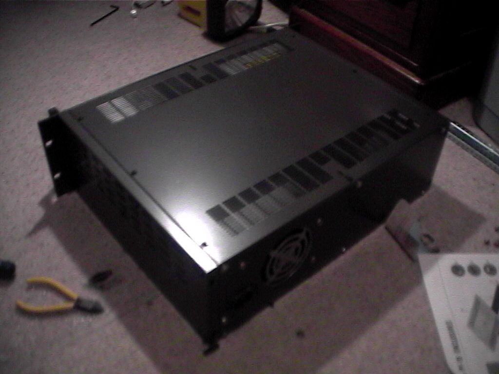
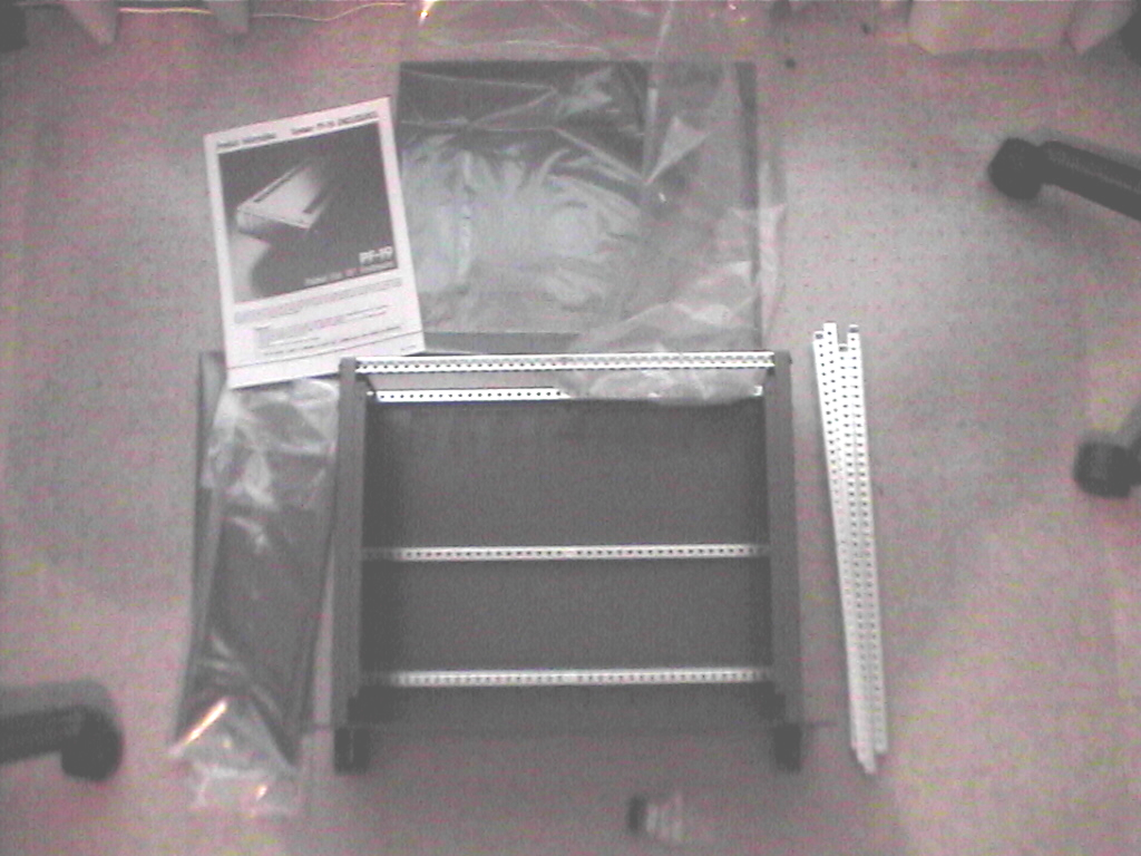
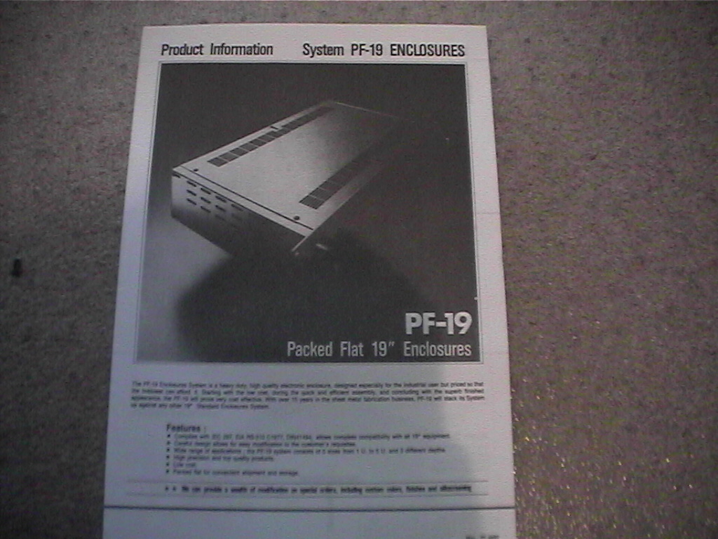
This is a picture of the rack case kit that i bought from a local electronics store. It doesn’t have to be a specialty computer store because servers are not the only thing that is mounted in the standard rack mount. It is a very basic case and although it may seem expensive, it is a fraction of the cost of a “specialized” computer rack mount case.
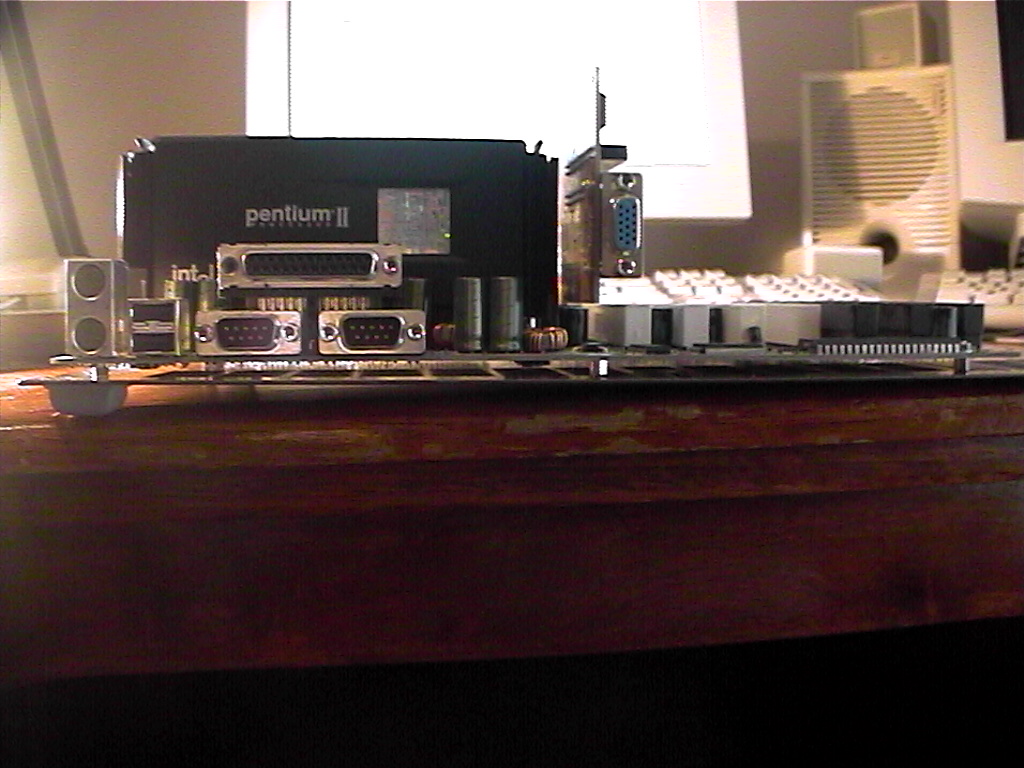
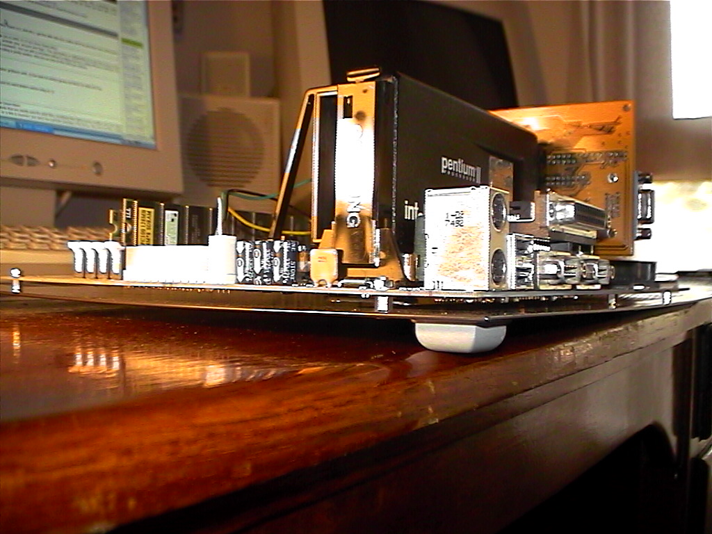
The first thing that i did was mount the Motherboard onto the base of the case. You cannot simply screw it straight onto the base because the metal case will short circuit the contacts on the bottom of the motherboard. Instead what i had to do was use spacers (your existing computer case would have used them i am sure) to keep the board above the metal casing.
I did have to drill a few holes in the bottom panel of the case. This is very easy though after you lay the motherboard on top and use a pen to mark the holes to drill. You can then use one long screw through the case, the spacer and then the motherboard where you can use a nut and washer to secure the board.
This does raise an important point which must be carefully followed throughout all these steps VERY carefully. Make sure that you keep all metal shavings and filings away from your computer components! If metal shavings get into your computer components you can pretty much kiss them goodbye, so be very careful and always use a vacuum to clean up any shavings you make, especially before test fitting any components!
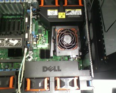
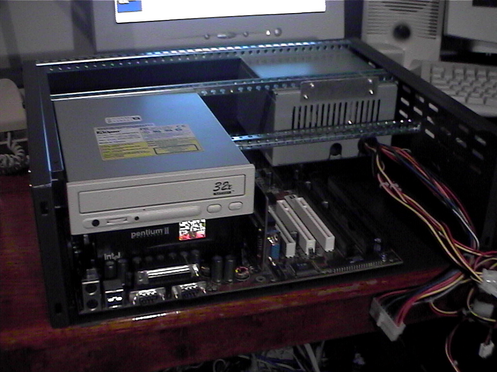
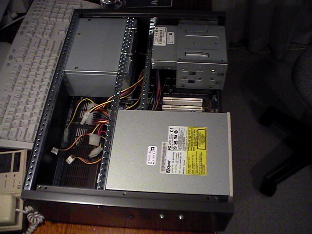
The first item that i chose to mount was the CD-ROM. This was because my CD-ROM is quite large and so it’s positioning was very important. As you can see it is large even by normal CD-ROM standards. I decided to mount it over the top of the CPU as the height was perfect.
For those of you who are thinking heat-wise maybe this is not such a good idea i thought about this! While the CD-ROM is not being used (eg. there is no cd spinning in it) it will generate very little heat, if any. And this being a server the cd should not be spinning very often at all.
I mounted the CD-ROM using one of the drilled cross bars underneath and by getting some rectangular aluminum tubing and screwing that to the side of the case and the CD. I also had to make a small right-angled bracket to screw the other side of the CD to the cross bar.
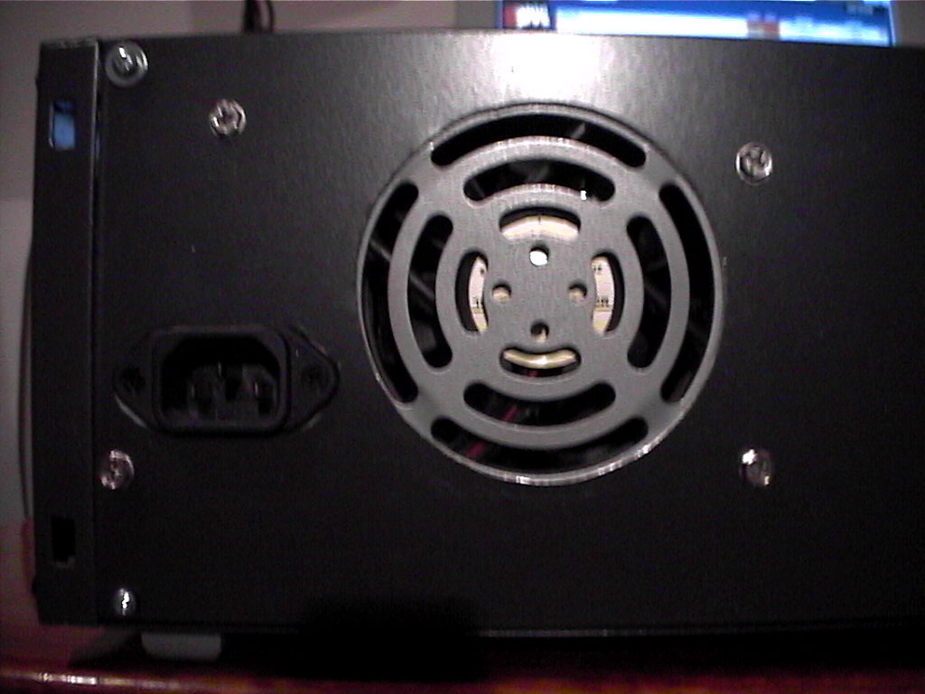
I also decided to mount the power supply at this stage. This is at the back of the case with the plug holes facing out the back. I put another cross bar in and made a strip of metal that allowed me to put screws into the cross bar and into the back of the power supply. I decided to screw the front of the power supply to the back panel of the case.
To make the back of the case strong enough to be used as a support i put in a cross bar at the top and bottom at the back and screwed the back panel on.
Note that the CD is mounted just behind the front panel and the socket and fan grill of the power supply just protrude through the back panel.

Now we have some work to do. I had to cut away the back panel to allow the fan and the power socket to protrude through the back. I also had to drill holes to allow the power supply to be screwed to the back of the case.
The case i bought had a steel main chassis, and aluminium front and back panels. The easiest way to cut this is to carefully mark where you need to cut using the components to trace around and measure off. Then because i know i probably made a mistake i drill a fairly large hole (say 9mm diameter) in the middle of the object i want to cut out. Then i test fit it, see how far away everything is and then start cutting the rest of the metal out.

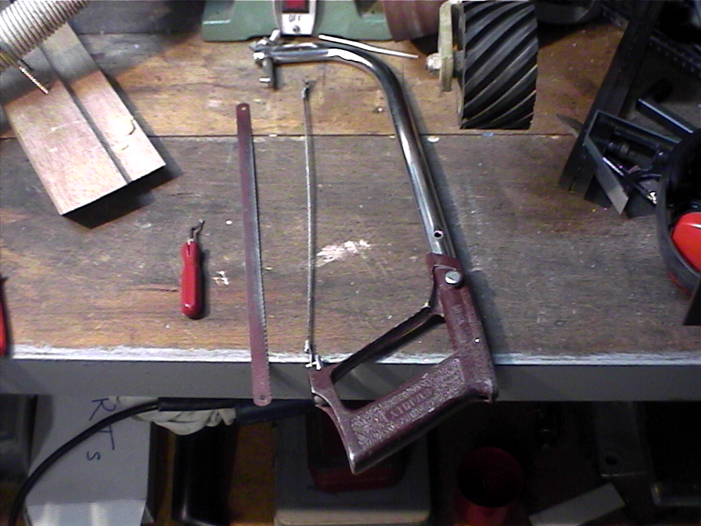
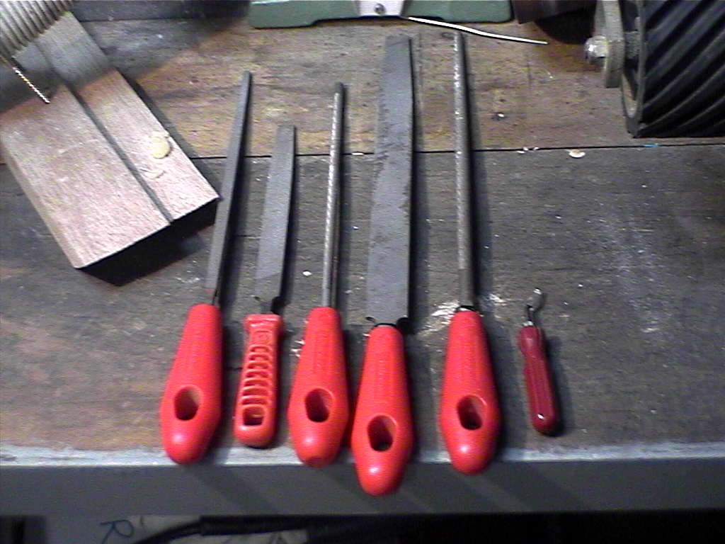
The best tools i found the cut out holes were files and a saw with a removable blade. These are both pictured on the left. The steps are as follows:
- Drill a hole in the area you want to cut big enough for the saw blade to fit through it.
- Unscrew and remove the blade from the saw. Thread the blade through the hole and then screw it back into the saw again. Use this to cut a rough outline of the hole (go inside the line not outside!).
- Use the files to tidy up your messy cutting and make any tricky little curves or corners needed etc.
The blade that i have attached to the saw in the photo is actually more like a fine file than a blade. It is round and lets you cut very tight curves and corners which is very handy.
The tool to the right of the files is used to bevel the edges of the cuts you make. This is to remove sharp edges and generally neaten things up a little. Think about how many cuts you get going into your existing computer case and then imagine what it would be like if the case was smaller, like this rack mount case…
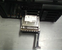
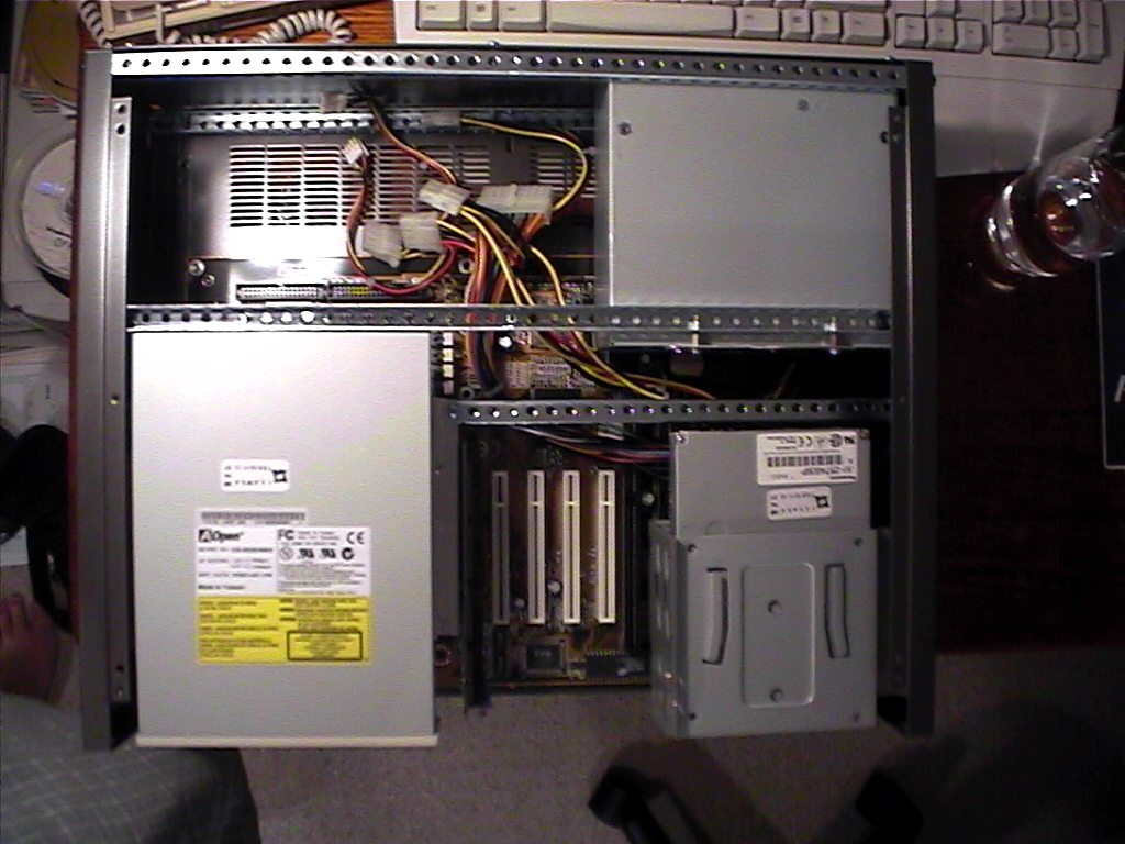
Next up to install was the floppy drive. This was actually fairly easy. Firstly i pinched the metal drive bay from my old computer case. This can fit both the floppy drive and 2 hard drives, so that is good enough for now. Again i used some of the square aluminum tubing cut into 2 lengths. One was for the side and the other underneath the drive bay.
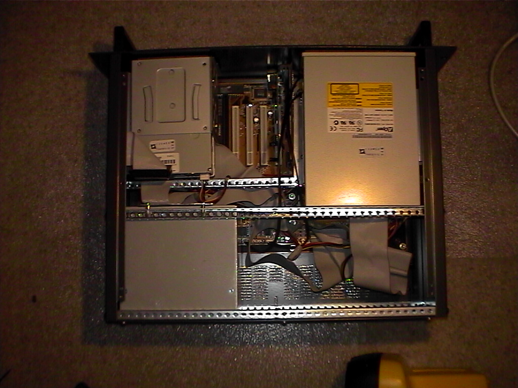
This setup gives me just enough room to let the wires out of the back of the power supply and plenty of room for 2 HDDs as the picture shows. This also leaves plenty of room to fit more PCI cards if they are needed, although it does cover an ISA slot or two, but who uses ISA these days anyway? 🙂
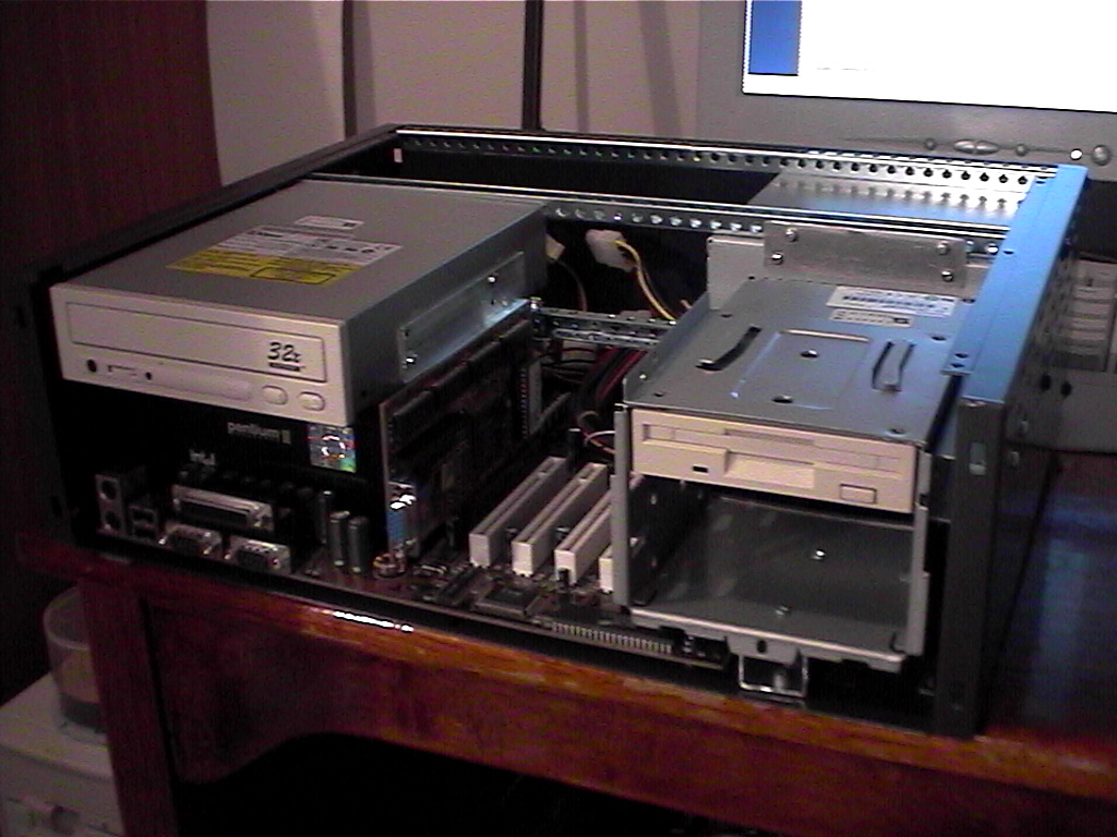

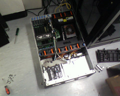
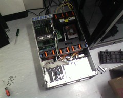
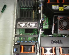
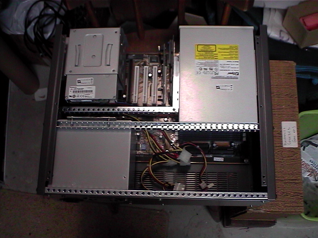
I now have all my major parts nicely placed around the case. The top picture shows nicely how everything is arranged in the case. This arrangement does have it’s problems however. The damn power cable is a few cm too short!
No matter. I will have to lengthen it by cutting, lengthening and resoldering the wires. That is easier than it sounds, but still rather annoying! All the other power cables reach nicely and so do the IDE and floppy cables. I cannot move the power supply now because i have already cut the back panel. Besides as the overhead view shows there is now a large amount of space behind the CD there which could be put to good use with extra drives or even just a fan.
I am now quite happy with the installation of the components.
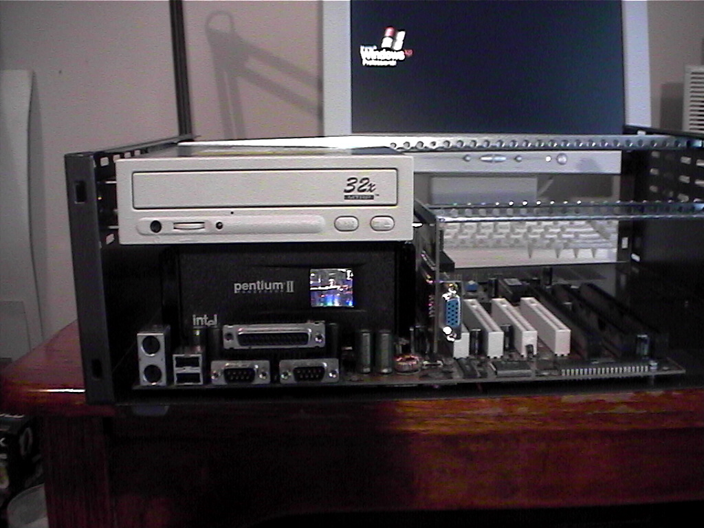
The next thing to do was to cut the holes in the front panel for the floppy, network card, graphics card, cd-rom, keyboard plug, mouse plug and the on and reset switches. I am also considering putting in an LCD screen so i will have to cut that hole as well.
An LCD screen will allow me to monitor things like CPU temperature, number of connections, network traffic etc. Again i used the same technique as for the back panel where i drilled a hole, used the hacksaw to roughly cut the hole, and then filed it all nice and smooth and clean.

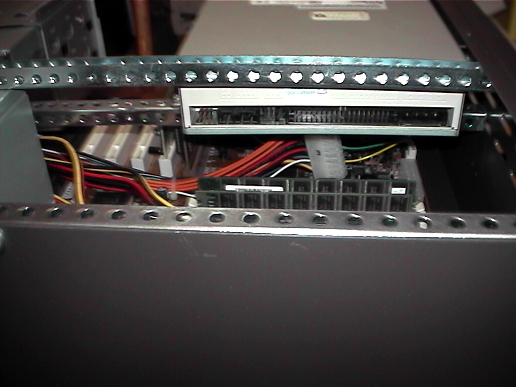
I had to lengthen that main power cable by about 2 inches to make sure that it would actually reach the socket on the motherboard. It was quite annoying to do! I matched all the colours of the wires, and heat-shrinked each one so that they wouldn’t make contact with each other. I then used zip ties to keep the wires in a nice bunch together. It is important to do this to allow more air flow around the box and just to keep things a bit neater. As the pictures show the cables appear to be reasonably neat in the end.
Finally i finished cutting the front panel. I also drilled 2 holes, one for the power button and another for a red HDD activity LED. All the cables fitted nicely through the front panel so i was very happy.
Putting all the cables into the components (eg. the HDD, floppy etc.) was a little bit tricky, but everything fitted quite nicely in the end. You just have to make sure that you don’t get things tangled up, and which cables go over and under various things. There is still more than enough space for another 3 PCI cards and 1 ISA card, as well as room in the mount for another HDD. In the back corner i think another 3 HDD’s could fit quite easily.


Finally i have finished! The case is all together and it looks quite nice i think. There are plenty of ventilation holes in the top to allow the hot air to escape. There are also a number of holes in the sides and base to allow air to flow as well. I may yet need to put in a fan, but i will put it through some testing to see whether this is the case or not.
Well i hope that this tutorial has been informative for everyone and the pictures and steps i took clear enough for you. I hope as many of you as possible can do this, it really isn’t all that hard, just a bit time consuming. It is good fun running a server, and it helps the community, so why not do it today?! 🙂 Good luck!